Iranian Classification Society Rules

< Previous | Contents | Next >
Section 25 Securing Devices
2501. Application
1. The requirements in this Section apply to tests and inspection for the type approval of securing de- vices, which will be approved by this Society for the safe carriage of cargoes, in accordance with the requirements in Pt 7, Ch 4, 1002. of the Rules and Pt 7, Annex 7-3, 7. (2) (B) of the Guidance, etc.
2. Raw forgings or castings are to be approved their manufacturing process by the Society in accord- ance with the requirements in Pt 2, Ch. 1 of the Rule.
2502. Type tests
1. Type tests to determine the breaking or proof loads are to be carried out on at least two saples of each item used in the securing system. The relationship between minimum design breaking load and safe working load is to be as indicated in Table 3.25.1.
Table 3.25.1 Design Braking Loads and Proof Loads
Item | Min. design breaking load | Min. proof load | ||||
≤40 | >40 | ≤40 | >40 | |||
Lashings | Wire ripe | 3 × | - | - | - | |
Rod | mild steel | 3 × | 1.5 × | |||
higher tensile steel | 2 × | 1.5 × | ||||
Chain | mild steel | 3 × | - | |||
higher tensile steel | 2.5 × | |||||
Fittings and securing devices | 2 × | + 40 t | 1.5 × | + 20 t | ||
NOTES: 1. Higher tensile steel is defined for this purpose as steel having a yield stress not less than 315 N mm (32 kg mm ). 2. Breaking and proof loads for lashings of material other than steel will be considered. | ||||||
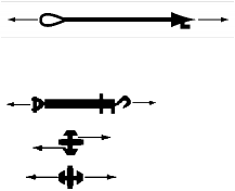
2. The Surveyor is to be satisfied that the design and materials of the fitting are in accordance with the approved plans. The mode of load application is to represent as closely as possible the in-serv- ice operational modes. Jigs are to be employed where necessary in order that satisfactory simulation is obtained. For guidance purposes, test modes which are required for the more commonly used fit- tings including vehicle securing device are shown in Table 3.25.2.
3. In the interests of standardization of the strength of container securing fittings and lashings, safe working loads in accordance with column 4 of Table 3.25.2 are recommended.
4. For acceptance, no permanent deformation (other than that due to initial embedding of component parts) is to be induced by test loads up to the proof load given in Table 3.25.1.
5. Where one of the test samples fails before the design breaking load is reached this can be ac- cepted, provided:
(1) The failure load is not less than 95 percent of the design breaking load.
(2) An additional sample is tested satisfactorily.
(3) The average failure load of the three samples is equal to or greater than the design breaking load.
Guidance for Approval of Manufacturing Process and Type Approval, Etc. 2015 159
![]()
![]()
![]()
![]()

Table 3.25.2 Test Loads and Test Modes
Item No | Description | Required test modes | Recommended minimal in tonnes | ||
SWL | Proof load | Breaking load | |||
1 | Lashing rod (H.T.S) | Tensile load | 25 | 37.5 | 50 |
2 | Lashing rod (M.S) | 18 | 27 | 36 | |
3 | Lashing chain (H.T.S) | 10 | - | 30 | |
4 | Lashing chain (M.S) | 8 | - | 20 | |
5 | Lashing steel wire rope | 12 | - | 36 | |
6 | Turnbuckle | Tensile load | 25 | 37.5 | 50 |
7 | Twistlock (single) | Shear load | 20 | 30 | 40 |
Tensile load | 25 | 37.5 | 50 | ||
8 | Twistlock (linked) | As for item 7+ tensile load | 5 | 7.5 | 10 |
9 | Midlock | Shear load Tensile load | 20 | 30 | 40 |
25 | 37.5 | 50 | |||
10 | Stacker (single) |
| 20 | 30 | 40 |
11 | Stacker (double) | As for item 10+ tensile load | 5 | 7.5 | 10 |
12 | Flush socket | Pull-out load | 25 | 37.5 | 50 |
13 | Pedestal socket | Pull-out load | 25 | 37.5 | 50 |
Tangential load | 20 | 30 | 40 | ||
14 | 'D' ring | Tensile load | 25 | 37.5 | 50 |
15 | Lashing plate | Tensile load | 25 | 37.5 | 50 |
16 | Penguin hook |
| 18 | 27 | 36 |
17 | Bridge fitting |
| 5 | 7.5 | 10 |
18 | Buttress |
| See Note 5 | ||
(Notes) 1. For items 6, 14, 15 and 16 where specially designed for use with chain or wire rope lashings a less SWL may be considered. 2. For items 8, 11 and 17 the recommended minimum loads quoted in the Table refer to the fittings when employed in a location in container stacks which do not transfer load to an adjacent slack. Where items 8, 11 and 17 are fitted in line with a buttress/shore support at stowage sides, test loads are to be determined in association with Note 5. 3. For items 12 and 13, where multiple flush sockets or pedestal sockets are involved test loads are to be applied simul- taneously to each socket opening which can be loaded simultaneously in service. 4. For item 15, where multiple lashing points are fitted in one deck plate fitting, testing is to bè similarly arranged as for Note 3. 5. For item 18, test loads for buttress fittings are to be determined by detailed consideration of the individual stowage arrangement proposed in association with Table 3.25.1. 6. Where special containers are used consideration will be given to the required minimum loads. | |||||
160 Guidance for Approval of Manufacturing Process and Type Approval, Etc. 2015
![]()
![]()